PAGE 2
Mounting the powertrain into the Fiero
The only real concerns as far as Fiero body chassis clearance to the engine are the battery tray and right frame rail. The battery tray could probably stay but would not have allowed much room to access the cooling system or serpentine belt so it was removed. The notching of the frame rail was necessary but the original wall can remain which allows for external reinforcement to be added to this section in the wheel-well side.
![]()
There are no clearance problems on the transmission side of the powertrain installed in the car.
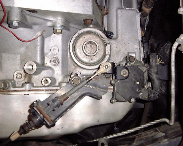
Automatic Shift Linkage and Cooler Lines
After the powertrain and cradle are mounted into the vehicle, there are several different things you can start off with doing. As I was waiting on part to be shipped to my door, I elected to do the transmission shift linkage. The stock Fiero 125-C auto trans shift cable, cable bracket, shifter, and shift lever were all used. Only the cable bracket and lever needed to be modified. The stock cable bracket needs to be unbent and flattened out, and needs a hole drilled, so it mounts to the transmission as shown below:
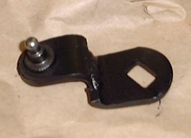
The stock Fiero shift lever needs to be cut down and re-welded offset to look something like this in order to allow the stock Fiero shifter to access all gear positions:
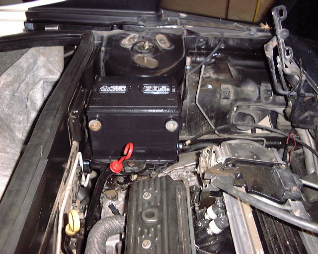
Battery and Battery Tray
The battery can be mounted almost anywhere in the vehicle. Most people elect to mount it up in the front trunk compartment area but this requires that a special battery mounting tray either be built or purchased, as well as cables run back to the engine. I elected to mount the battery in the engine compartment. The reason was 3-fold. Because the engine sits so far to the right in the vehicle, this can present a center of gravity balance problem from right-to-left. I also noticed that the area above the shifter assy was quite empty and looked awkward. Finally, putting a battery in this area would allowed for the use of the stock Fiero battery cables, and allowed me to use the stock Fiero battery tray. Only a couple of pieces needed to be welded to the tray after it was trimmed, and then the whole assembly was bolted into the vehicle. Battery cooling was now handled by one of the stock 2.8L Fiero blower vents which had a 90 degree pipe clamped to it so it would direct cool blower air to under the battery.
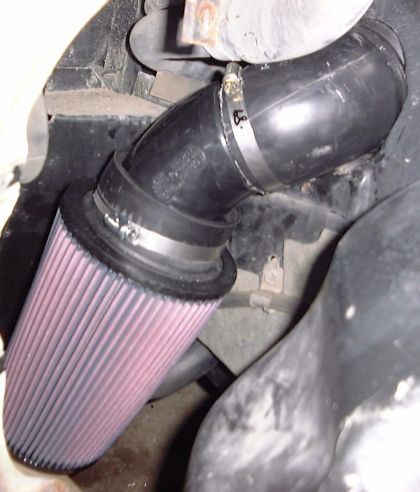
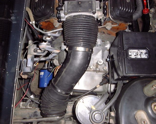
Air Intake Induction
Now that the battery was mounted, it was time to route the air induction plumbing. After the stock Fiero air canister filter and water seperator were removed, it was time to piece the system together. The key to making horsepower is allowing the engine you have to be able to breathe freely, and to draw air from the coldest possible source. While I have seen some engine conversions mount an open element filter near the throttle body in the engine compartment, this is not a good source for clean, cool air as heat from the exhaust system tends to flow up from under the trunk area in order to escape out the vent grilles that are located near the rear window. The last thing you want is your air filter right in the path of this rising heat. Now, to get around this problem, some people have opted to use the stock Fiero induction system. To put it bluntly, the stock Fiero induction system flowed barely enough for the stock 2.8L V6, let alone anything that demanded more. The biggest bottleneck in the stock induction system is the water separator, which has too many small, sharp bends designed to keep out debris and water. This is no good for performance. With all that stuff gone, I was able to use a combination of stock TPI V8 and late model GM Vortec truck 3.5" plastic induction tubing, along with an open element K&N Filter. The K&N filter is mounted in the same location as the stock water seperator allowing it to eascape hot air and road debris but allowing it to breathe enough cool air to feed this engine.