Fiero Fuel Pump "HOT WIRE" rewiring instructions
WHY?
The power circuit for the fuel pump in the Fiero has to travel through several connectors before making it to the fuel pump. The length of the circuit is also quite long resulting in significant voltage drop before making it to the pump. While this is fine for an OE pump; this setup can be troublesome for high-performance applications especially those using aftermarket, hi-output fuel pumps.
The power for the fuel pump must travel from the fuse box (located under the steering column) back to and thru the C203 connector out to the fuel pump relay, then back inside the car again thru the C203 connector than then out to the 3-wire connector which connects the circuit to the fuel tank. The purpose of this "hot wire" rewiring instruction is to shorten the circuit thus giving the power a much shorter path to the fuel pump.
METHOD 1: Moderate and High Performance applications
The 3-wire connector used in 85-88 Fieros that connects the sending unit/tank to the vehicle harness contains a black (or black/white) wire which is the ground and a tan/white (or grey) wire which is the power supply to the pump. For this method we are going to modify the wiring on the vehicle side of the harness connector so no modifications to the tank/sending unit wiring is required.
1) Leaving the ground wire intact, splice in an additional 14 ga. wire by skinning back the insulation on this wire and soldering in the additional wire. Since this is a ground connection, corrosion of the exposed connection should not be a concern. But the connection/splice should still be wrapped in electrical tape. The other end of this additional wire you just spliced in should be connected to a clean chassis ground via a crimped-on ring terminal. This purpose of this step is to reinforce the ground circuit to the fuel tank sending unit.
2) The fuel pump power supply wire on the vehicle side of the harness should be cut about 3 inches from the 3-wire connector (to leave enough wire on the connector for you to work with). Strip off about 3/8" of the insulation from both ends of the wire you just cut.
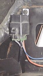
3) Obtain a 4 or 5 terminal relay from the junkyard or auto parts store. A weather-proof model is preferred (can be found on most late 80's and early 90's GM vehicles) as seen below. Whichever relay you get should have the same basic circuits: 2 terminals for the electromagnetic coil control and 2 or 3 terminals that get switched inside the relay. For the purpose of this instruction I am going to use the standard terminal identifications found on most relays. Use 12 ga. wire for all power connections and 16 or 18 ga. wire can be used for the relay's coil control wiring. All spliced connections should be soldered and sealed using heat-shrink tubing. If any crimp splice or terminal connectors are used they should be of the heat-shrink covered type so the connection is shielded from the elements.
4) Connect one of the relay's coil control terminals (term 85 or 86) to ground using 16 or 18ga wire. Connect the other coil control terminal (term 85 or 86) to the fuel pump power wire coming from the vehicle wiring harness (tan/wht or grey).
5) Connect the common switch terminal of the relay (term 30) to the tan/wht (or grey) wire going to the 3-way electrical connector that hooks to the tank harness via 12 ga wire.
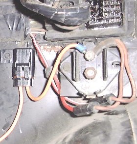
6) Connect the N.O. (normally open) terminal of the relay (term 87) to a 12 ga. wire leading to an in-line weather-proof fuse holder. NAPA sells GM-type, weather-proof blade type fuse holders under p/n 782-3127; like the one pictured below.
7) The other wire coming from this fuse holder can be connected directly to the power distribution block under the C500 connector in the Fiero (as seen above), or directly to the battery terminal on the back of the alternator for maximum performance via a crimped and soldered on ring terminal.
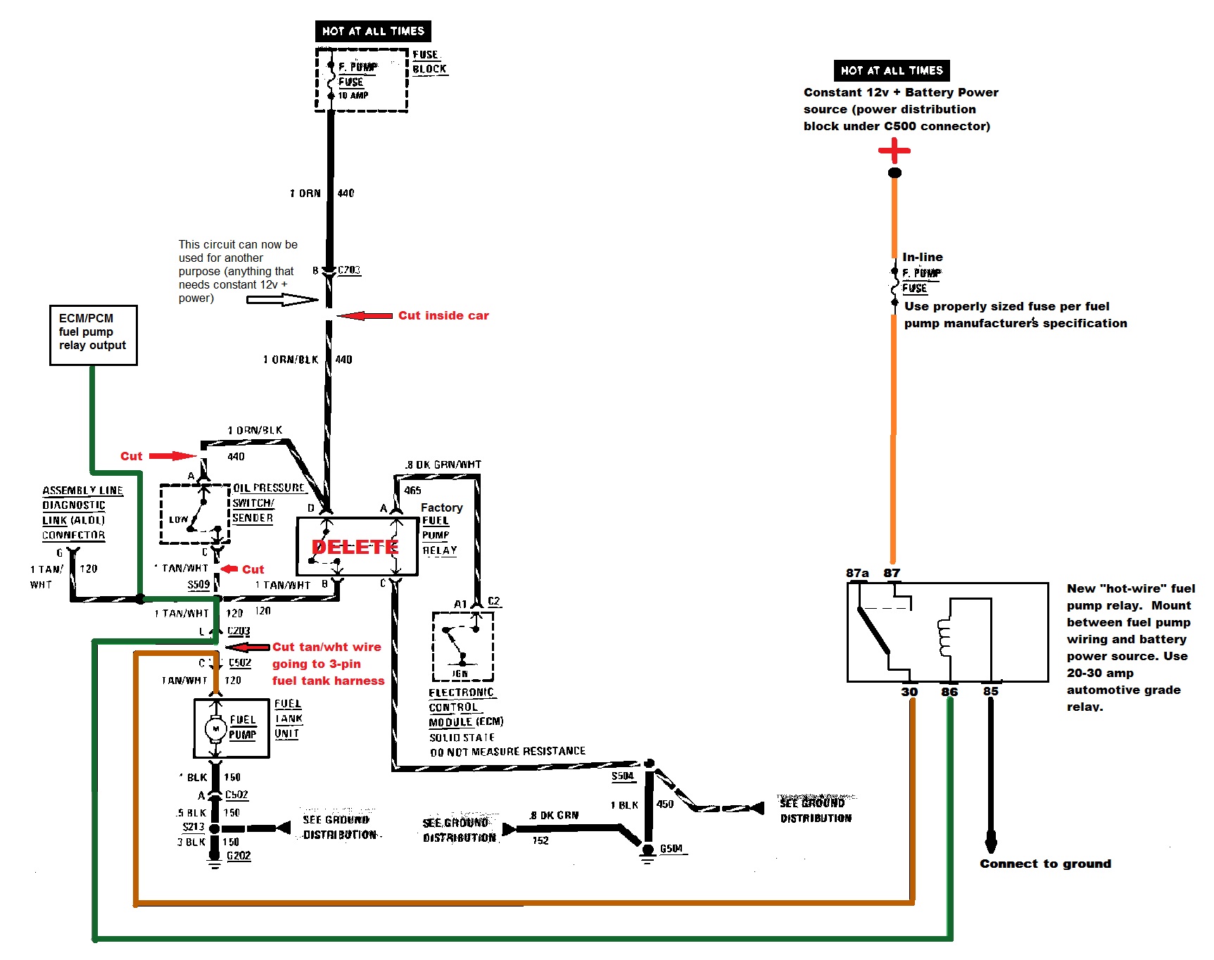
8) Now all that needs to be done is wiring up the ECM/PCM's fuel pump relay output control to the Fiero wiring. Simply connect this circuit to the existing Fiero tan/wht (or grey) fuel pump power wire going thru terminal L of the C203 connector. NOTE: DISCONNECT/DO NOT USE the oil pressure fuel pump backup switch when wiring the fuel pump circuit in this way. To do this, simply cut or disconnect the tan/wht or grey wire coming from the oil pressure sender connector.
Below is a diagram to aid in this modification.